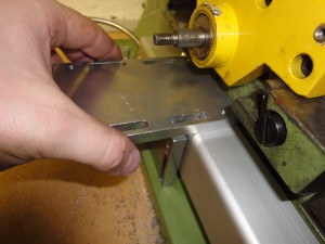
Here’s a few pictures I took as I went along installing a DRO system on the WM-18.
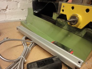
Y Axis first, as I suspected it would be the most annoying. The base of the mill has a small vertical face, and then a slanted section to the benchtop. The scales I have use a 2-part cover which gives a backing plate to attach the scale to.
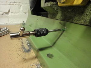
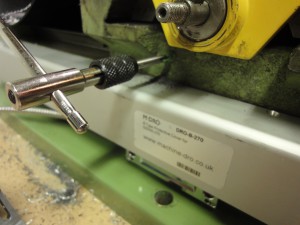
The first installation step is to attach the backing beam in the correct location, taking the travel of the saddle into account so you don’t destroy the scales the first time you travel the y-axis ! Once the position is determined, take a deep breath and start drilling. Take a deeper breath and get the tap out – note how the base of the mill is nicely filled and painted – the sides of the saddle are left ‘as cast’.
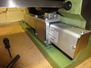
One hole drilled, then alignment can be checked to ensure parallel movement with the saddle travel. Second hold drilled and tapped, and scale test fitted:
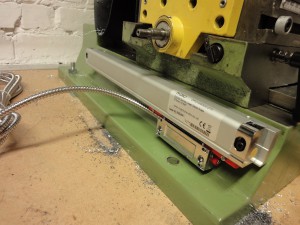
The scale needed about 10mm of shim on the top to get the backing plate vertical. Once that was all looking good the next step is to connect the saddle to the reading head. Various brackets are supplied:
I cut one of the brackets down on the bandsaw, then ran an endmill across the top to neaten it up. Check position and drill and tap again. As the casting is pretty rough it proved a bit tricky to get through the skin (and sand, probably!). Tap came out again:
Then followed about an hour (!) of shimming, adjusting the rough surface, more shimming, packing, and general fiddling to get everything square and smooth. There is clearance between the bracket and scale cover, believe it or not !
Next – the X axis !
« Warco WM-18 Arrives ! Warco WM-18 DRO Installation – X Axis »
