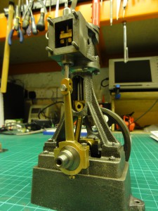
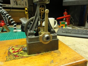
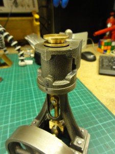
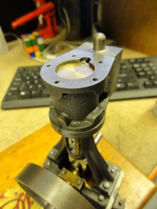
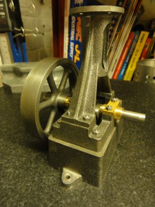
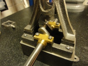
Finally – it lives ! Some tidying up to do – but very pleasing !
http://www.rootprompt.co.uk/wp-content/uploads/2010/09/10v.movTag Archive: Stuart 10v
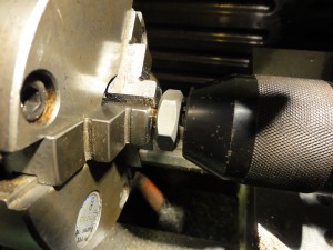
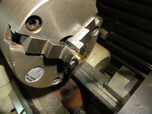
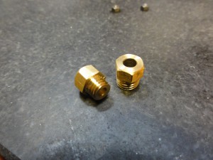
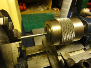
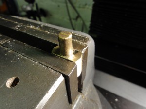
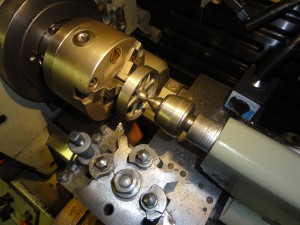
One of the final jobs is creating two gland nuts to seal the cylinder and valve chest. Stuart supply a section of hex bar for this. After turning down to the required diameter, I used the drill chuck in the tailstock to keep the die square as I cut the thread.
Removing the die and using it backwards allowed me to get the thread nice and close to the shoulder:
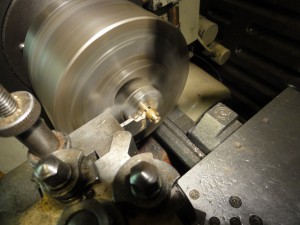
With both ends of the hex bar threaded appropriately, I could then drill and ream for the valve rod – the cylinder gland needs to be larger, but that can be done after parting off:
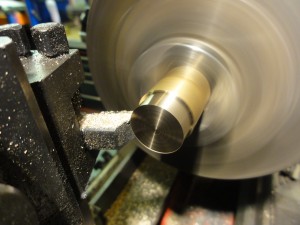
The finish left after parting off was quite acceptable – it remained to use a small file to round off the sharp edges of the hex bar for a nicer finish:
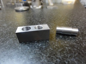
The part left in the chuck could now have its bore enlarged for the piston rod. Here’s the parts nearly finished – just some gentle filing to remove any final marks.
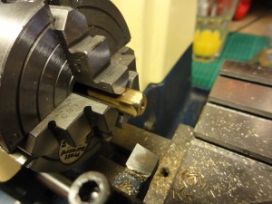
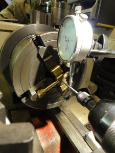
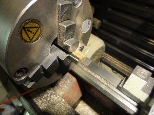
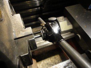
Fork end material mounted in the 4-jaw and having the boss turned on it – I used my height gauge to center the material in the chuck.
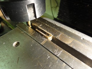
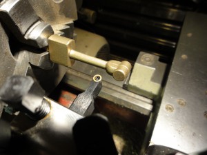
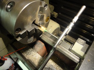
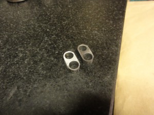
Scaring the poor 1/4 inch brass square to death in the milling machine. Here I’m running a 3mm slot drill through to create the fork (or the tines, maybe)
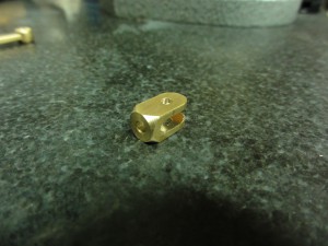
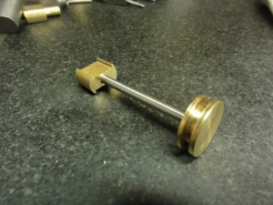
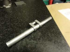
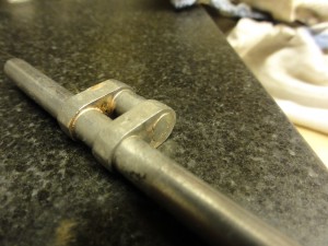
The fork end after some trimming and filing. I need to tap the 5ba thread into the boss to connect the valve rod.
Work now begins on the timing and valve bits. Here’s the eccentric after the usual filing to clean up and with the bore opened out to size. I chose to do that on the mill with a boring head.
However, I trusted the book again and opened the bore up to 16mm – instead of measuring the supplied stock for the sheave and working to that, so I had to turn down a new piece to fit my nicely bored hole – seem here being ‘parted off’ in the bandsaw !
And partial assembly. The book suggests a clever way of achieving the eccentricity required – placing a 3.5mm spacer on one of the jaws in the 3-Jaw chuck – this worked really nicely.
Something isn’t quite right here ! I’m no expert – but this doesn’t look right. When the crank is at TDC, the piston is clear of the cylinder.
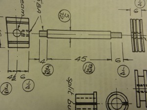
Here’s the page from the Pengwern book. Spot the deliberate mistake…
1 and 13/32 of an inch is actually 35mm (ish) – not 45 as is illustrated. Once that was sorted out, the engine now looks like this at TDC:
Starting work on the conrod. Mounted up via the chucking piece in the lathe, and then I’ve set the topslide over at an angle to match the taper. Gentle cuts to remove the casting marks and generally tidy the part up:
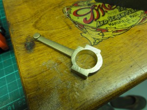
Once thats done, the conrod is mounted in the milling vice to drill the through holes. Doing this before splitting the part should hopefully help alignment. Here I’ve used a milling cutter just to flatten of the surface to allow for more accurate drilling. I’ve also used the edge finder to align the part accurately on the X axis under the spindle.
Moving to the lathe, I’m using a wiggler to get the part centred in the 4-Jaw for the drilling and facing operation.
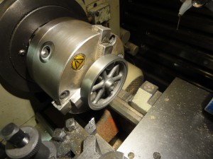
Once cleaned up by filing, the flywheel can usefully be mounted using the outside of the jaws in the three jaw chuck, and was fairly centrally aligned. This allows for gently tidying up all the accessible edges of the casting and sizing the hole for the crank shaft.
With that done, I mounted the flywheel on a scrap piece of 9/32 stock to perform the rest of the turning – hopefully that will ensure it’s nicely concentric when mounted on the engine. With only the setscrew holding it in place gentle cuts are the order of the day, and I’m using my new (to me, anyway) live centre to add support and prevent chatter.
Flywheel in position – starting to look like something now !
Moving on ! Turning the piston to fit neatly into the bored head of the cylinder:
And using the chucking piece to turn the crosshead down to fit into the standard:
Tapping the crosshead for the piston connecting rod – started by supporting with the tailstock to get it concentric, although you can’t see that here:
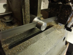
Using the corresponding die to cut the thread on the piston connecting rod – my pratt burnerd chuck is adequately accurate for this – alternatively a bush to hold the rod could have been made from scrap brass.
Completed assembly – I’ve followed the advice from the Pengwern book – cutting one fairly deep groove in the piston for graphited packing rather than 3 finer oil grooves.
After a poor silver soldering attempt some more 9/32 stock has been ordered for a second try. I’ve bonded the web blanks together with some cyanoacrylate to try and ensure concentricity. I’m also using a tip picked up from Markus Neeser (his website is here – lots of useful stuff). He suggests making a a small area of the crank pin a press fit into the web – hopefully preventing the solder escaping onto the pin.
Here are the webs again, being formed into shape by filing. I’ve lightly countersunk the holes where the pin will fit to ensure a tight seat on the shoulder. Careful not to go too far and undo the good work with the press fitting diameter of the pin !
And the assembly pre-soldering – the pin was a lovely press fit into the webs.
Post soldering – and then pickled in citric acid (in the form of cheap descaler tablets)
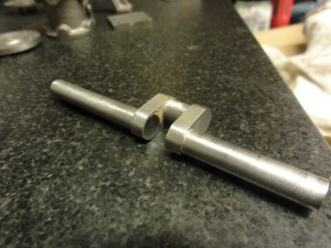
Cut the waste section from the middle of the webs with a hacksaw, and then clean up with a slot drill
And installed into the bearings:
